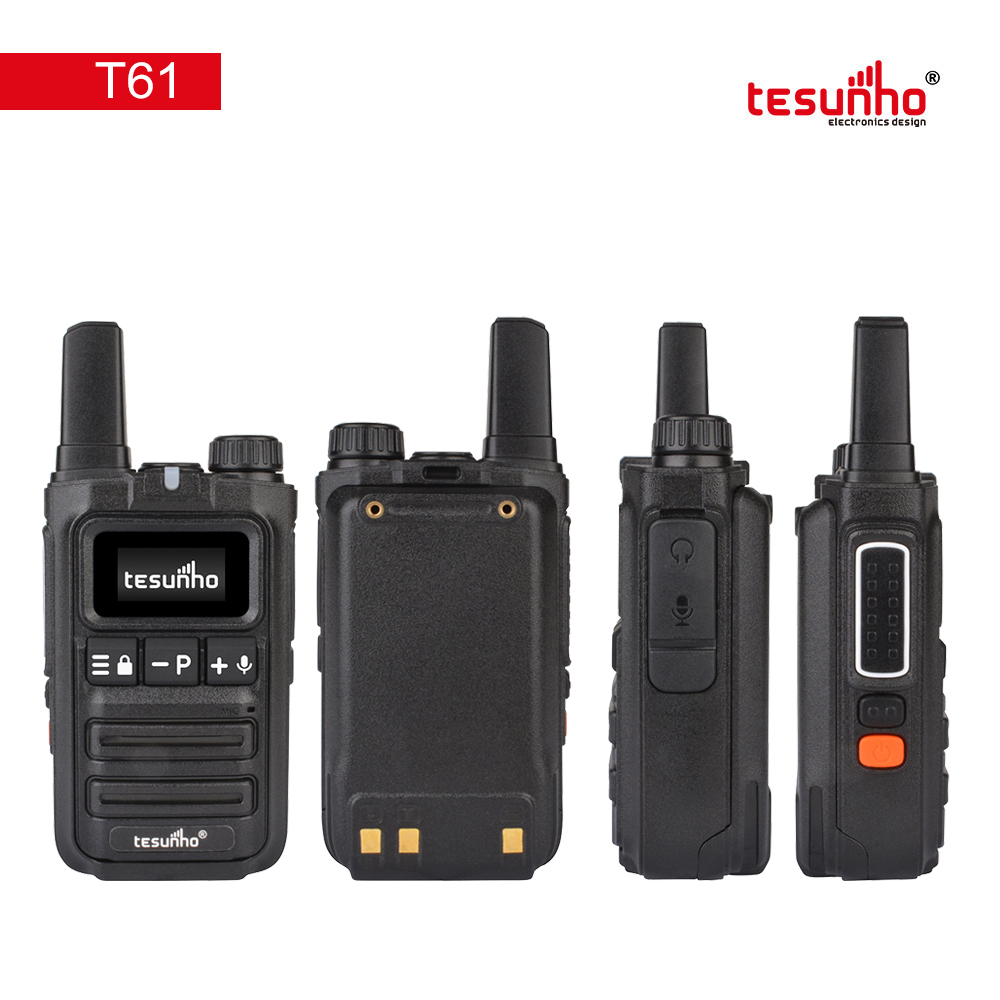
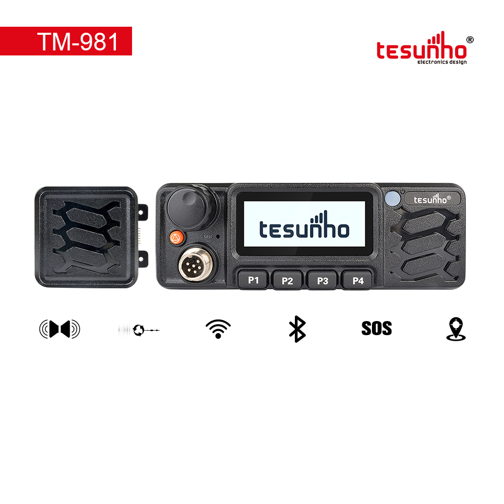
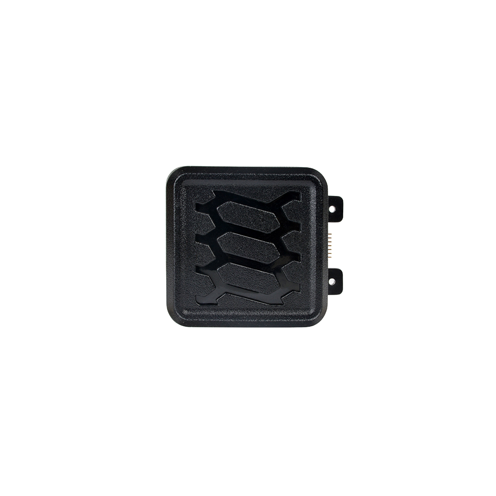
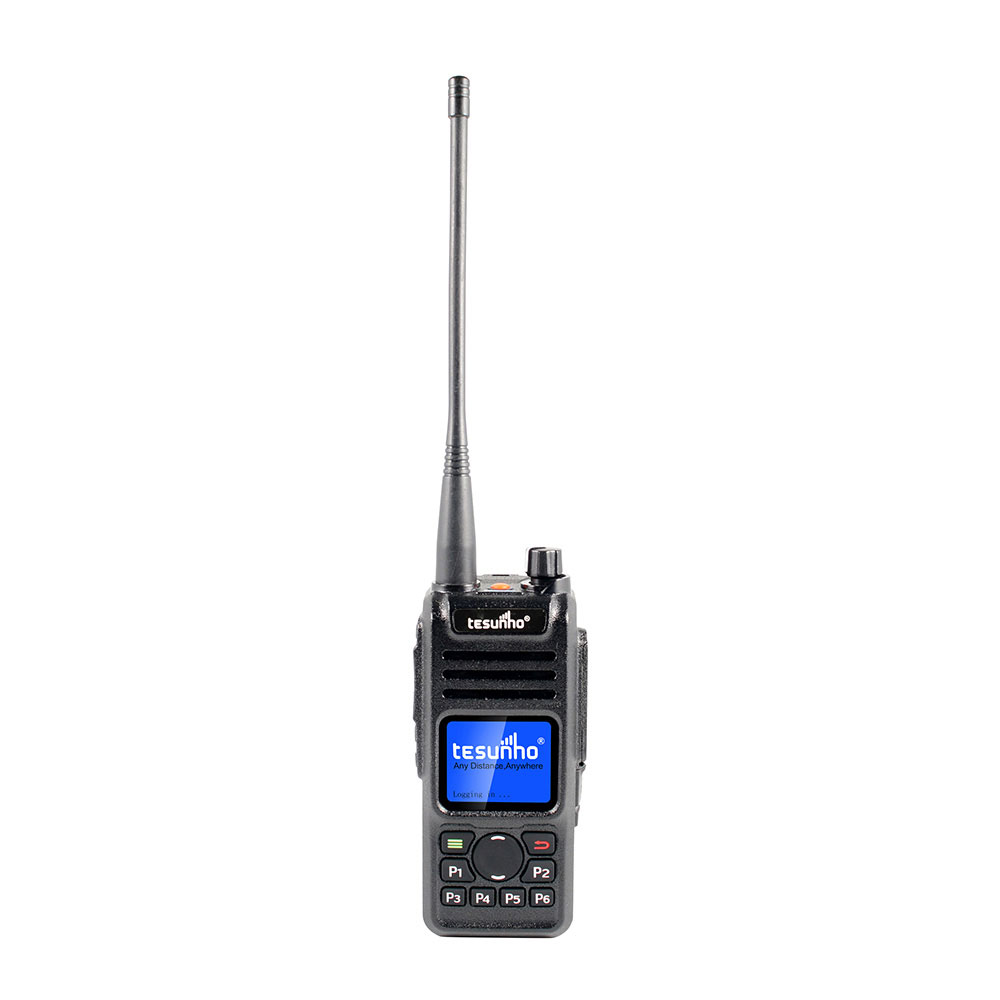
Diagram
No. | Part Name | No. | Part Name | No. | Part Name |
1 | Antenna | 6 | MENU Key | 11 | PF2 |
2 | Speaker | 7 | Down Key | 12 | Speaker Jack |
3 | Microphone | 8 | Up Key | 13 | Microphone jack |
4 | LCD Indicator | 9 | PTT(Push-to-Talk)Switch | 14 | Charging Hole |
5 | Power and Volume Control | 10 | PF1 | 15 | Micro SIM Card Slot |
Radio Display
LCD Icon
Icon | Name | Status |
| Battery | More bars indicate more battery power. |
| Battery charging | Red: charging. Green: fully charged. |
| Signal | More bars indicate stronger signal strength. |
| SOS | Transmit SOS or receive SOS. |
| GPS | GPS available, but no positioning success. |
| GPS | GPS positioning success. |
| Network availability | Normal network. |
| Key Lock | Keypad locked. |
| New Message | New message. |
| Records | PTT Records is open. |
| Monitor | Monitor the group which Icon shown at. |


